
What is BYOVD?
BYOVD (Bring Your Own Vulnerable Driver) is a technique where an attacker abuses a legitimate, signed but vulnerable kernel-mode driver to perform privileged operations.
Since kernel drivers operate at Ring 0, a vulnerability in one can potentially be abused to bypass security mechanisms and perform actions that would normally be restricted from user mode.
In this case, the vulnerable driver exposes functionality that can be abused to terminate processes, making it particularly interesting from a BYOVD perspective.
In this writeup, we’ll reverse engineer the driver, identify the vulnerable functionality, and analyze how it can be leveraged to achieve process termination from user mode.
Vulnerability Overview
Alinubx.sys is a vulnerable Windows kernel-mode driver that is listed in LOLDrivers as a driver capable of terminating processes.
The main security issue is the lack of proper access control when opening a handle to the driver's device interface. The driver does not adequately verify whether the requesting process has the required privileges before allowing communication with it.
As a result, an unprivileged user-mode process can obtain access to the driver and interact with its exposed functionality, including the ability to terminate other processes.
This makes Alinubx.sys an interesting example of a BYOVD scenario, where a legitimately signed kernel driver can be abused to perform privileged operations that should not be available to an unprivileged user-mode process.
Reverse Engineering
After loading Alinubx.sys into IDA Pro, I started by inspecting the driver's Imports from import tab.
I navigated to the reference for ZwTerminateProcess and followed its cross-references. This led me to a function that uses the following three kernel APIs:
- ZwTerminateProcess
- ObOpenObjectByPointer
- PsLookupProcessByProcessId
By analyzing this function, I identified the code path responsible for the driver's process termination functionality.
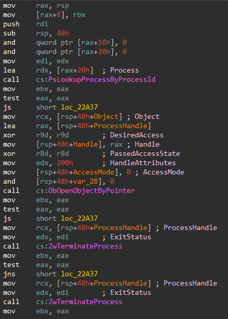
Now that the termination routine had been identified, the next step was to determine how user-mode requests reach this function.
Since the driver is expected to communicate with user mode through DeviceIoControl, I started tracing the driver's initialization from its DriverEntry routine.
In Windows kernel drivers, I/O request handlers are registered through the MajorFunction array inside the DRIVER_OBJECT structure. Each entry corresponds to a different type of IRP request, including IRP_MJ_DEVICE_CONTROL.
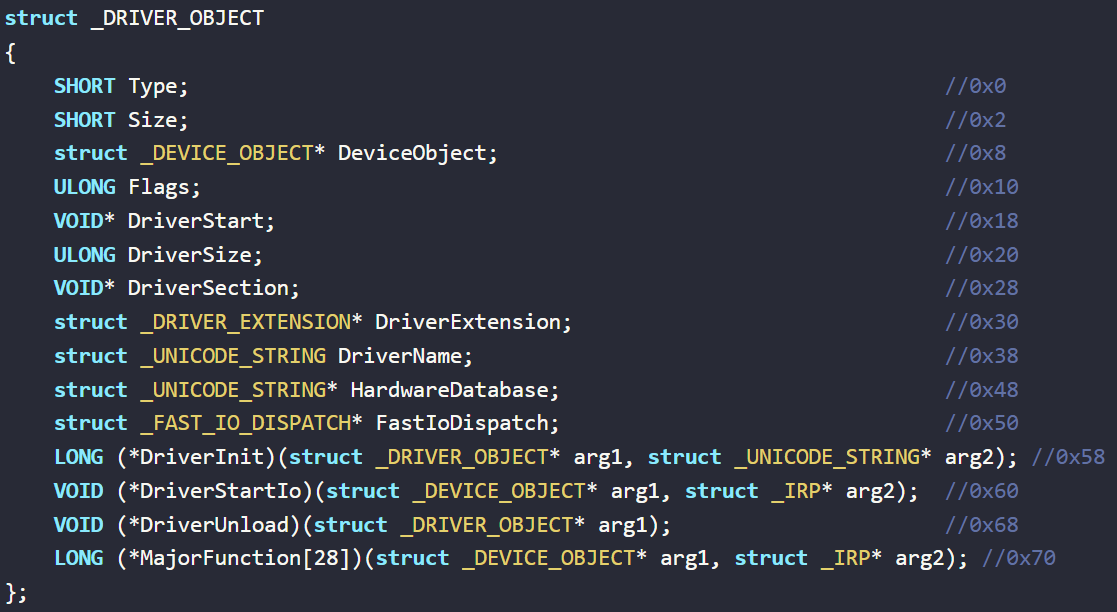
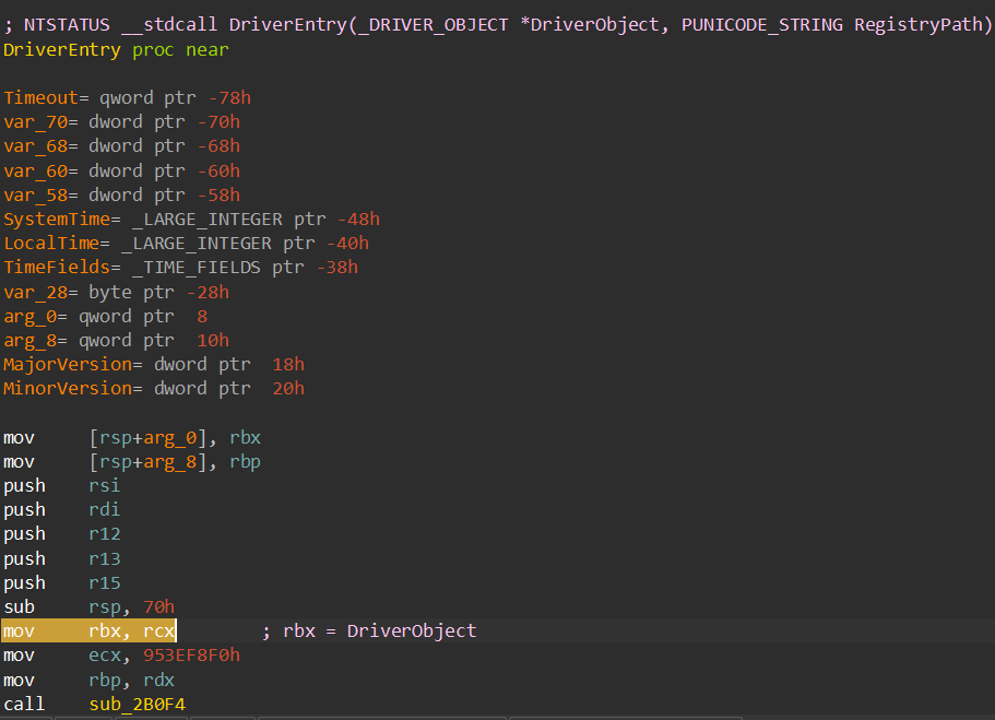
On x64 Windows, the first argument passed to a function is placed in RCX. Since the DRIVER_OBJECT pointer is the first argument of DriverEntry, it is initially available through RCX.
The driver first preserves the address of the DRIVER_OBJECT by moving the value from RCX into RBX.
The driver then initializes the MajorFunction array using the rep stosq instruction.
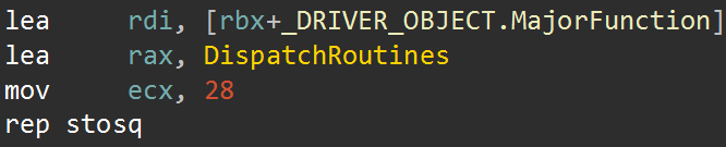
To do this, it first calculates the address of the MajorFunction field within the DRIVER_OBJECT. On x64, this field is located at offset 0x70, so the address is calculated as RBX + 0x70 and loaded into RDI:
lea rdi, [rbx+70h]
Next, the address of the driver's dispatch routine is loaded into RAX:
lea rax, DispatchRoutines
The MajorFunction field is an array of function pointers used to register the routines responsible for handling different IRP request types. The driver sets ECX to 0x1C (28):
mov ecx, 28
It then executes:
rep stosq
Since STOSQ stores the 64-bit value contained in RAX at the memory location pointed to by RDI, the REP prefix causes this operation to be repeated 28 times.
Therefore, the driver writes the address of DispatchRoutines into 28 consecutive entries of the MajorFunction array.
This means that the driver's IRP handling paths represented by these entries are all routed to the same DispatchRoutines function, which acts as the common handler for the driver's requests.
Analyzing the Dispatch Routine
We can now move into the DispatchRoutines function.
A Windows driver dispatch routine generally receives two parameters:
NTSTATUS DispatchRoutine(
  PDEVICE_OBJECT DeviceObject,
  PIRP Irp
);
The first parameter is a pointer to the DEVICE_OBJECT, which represents the device object associated with the request.
The second parameter is a pointer to an IRP (I/O Request Packet).
An IRP is a kernel structure used by the Windows I/O Manager to represent an I/O request sent to a driver. It contains information about the request and allows the driver to process it and eventually return a status to the caller.
Each IRP can contain one or more I/O stack locations. A stack location contains information specific to the current driver layer processing the request.
To access the stack location belonging to the current driver, the driver uses the Current Stack Location pointer from the IRP.
Identifying the Request Type
Inside DispatchRoutines, the driver obtains the address of the current IO_STACK_LOCATION and stores it in RSI.
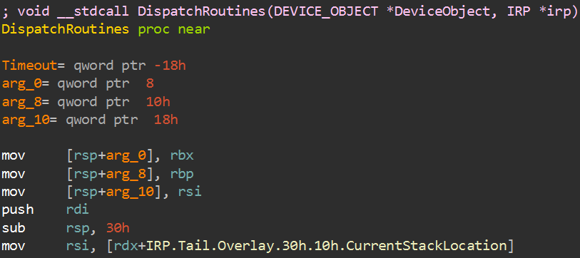
The first field of IO_STACK_LOCATION structure contains the MajorFunction value, which identifies the type of IRP request being processed.
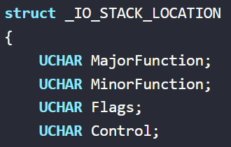
Some common MajorFunction values include:
IRP_MJ_CREATE—0x00IRP_MJ_CLOSE—0x02IRP_MJ_READ—0x03IRP_MJ_WRITE—0x04IRP_MJ_DEVICE_CONTROL—0x0E
As shown below, the driver compares the MajorFunction value with 0x0E, which corresponds to IRP_MJ_DEVICE_CONTROL.
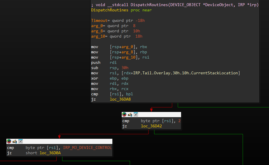
If the request is an IRP_MJ_DEVICE_CONTROL request, the driver transfers execution to another function, which I will refer to as DeviceIoControlRoutine.
This function receives the same two parameters as the dispatch routine: the DEVICE_OBJECT and the IRP.
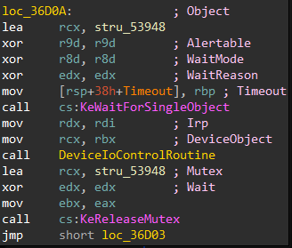
When we follow this function, we reach the code path that eventually calls the previously identified process termination routine.
The information required by this routine is supplied from user mode through the Windows DeviceIoControl API.
The relevant interface can be represented as:
DeviceIoControl(
  hDevice,
  dwIoControlCode,
  lpInBuffer,
  nInBufferSize,
  lpOutBuffer,
  nOutBufferSize,
  lpBytesReturned,
  lpOverlapped
);
We can now trace how each of these values is extracted from the IRP and used by the driver.
Identifying the IOCTL Code
First, the IOCTL code supplied by the user-mode application is loaded into EBX.
The input buffer length (InputBufferLength) is stored in R12, while the pointer to the input data supplied by the user-mode application is loaded into RDI.
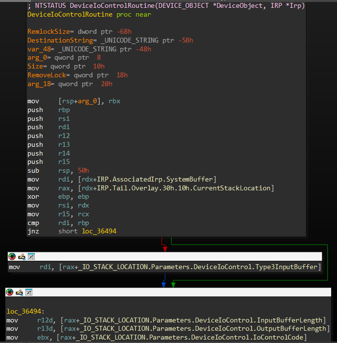
Since we already know that the TerminateProcess routine is the interesting execution path, we can work backwards from that call and determine which IOCTL request causes the driver to reach it.
As shown below, the value stored in EBX (IOCTL code) is first reduced by 0x222020, and then by 4.
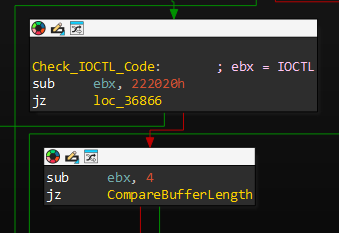
For the execution to reach the termination path, the result of this calculation must be zero:
IOCTL - 0x222020 - 4 = 0
Therefore:
IOCTL = 0x222024
So, 0x222024 is the IOCTL code that reaches the process termination functionality.
Identifying the Input Structure
Next, the driver validates the input buffer size.
The value previously stored in R12, representing the InputBufferLength, is compared against 8.
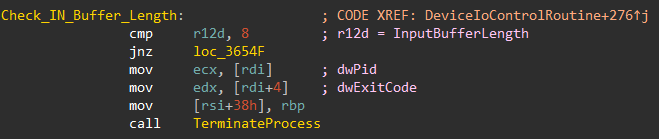
If the input length is 8, execution continues toward the termination routine.
This tells us that the driver expects exactly 8 bytes of input data for this request.
We can then look at how these 8 bytes are used.
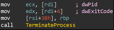
The data is split into two 4-byte values. The first DWORD is passed as the first argument to the termination routine, while the second DWORD is passed as its second argument.
Therefore, the input supplied through DeviceIoControl (Windows API) can be represented as a simple structure containing two DWORD members:
typedef struct _TERMINATE_REQUEST {
  DWORD val1;
  DWORD val2;
} TERMINATE_REQUEST;
Reaching the Termination Routine
We can now enter the TerminateProcess routine identified earlier.
The first important API call is PsLookupProcessByProcessId.
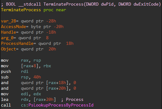
This function takes a process ID and returns a pointer to the corresponding EPROCESS structure.
The first value from our input structure is passed as the PID argument to PsLookupProcessByProcessId.
Therefore, the first DWORD supplied through DeviceIoControl API is the Process ID of the target process.
The driver then uses ObOpenObjectByPointer to obtain a handle to the target process object.
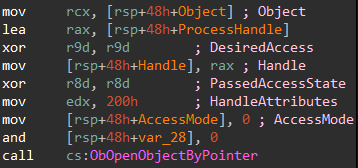
The resulting process handle is stored in the driver's local stack frame.
Finally, the driver calls ZwTerminateProcess.

The second DWORD from our input structure is passed as the second argument to ZwTerminateProcess, which is the process ExitStatus.
This allows us to reconstruct the complete request flow:
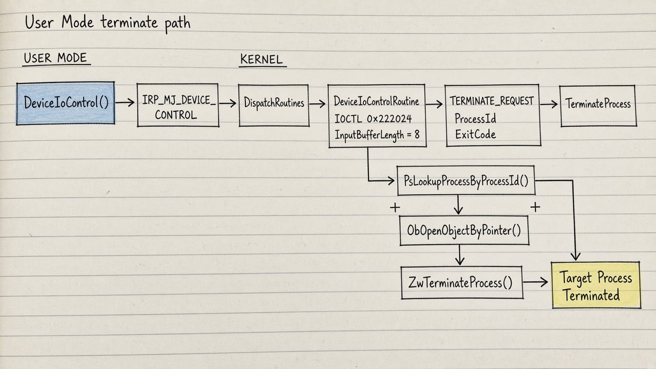
At this point, we have traced the complete path from a user-mode DeviceIoControl request to the driver's kernel-mode process termination functionality.
Conclusion
Thanks for taking the time to read this writeup.
During this analysis, we reverse engineered Alinubx.sys, traced its DeviceIoControl communication path, identified the relevant IOCTL and input structure, and followed the execution flow all the way to ZwTerminateProcess.
I also implemented a small proof-of-concept demonstrating how the vulnerable functionality can be reached from user mode. The source code is available on my GitHub: